
Look at the rings
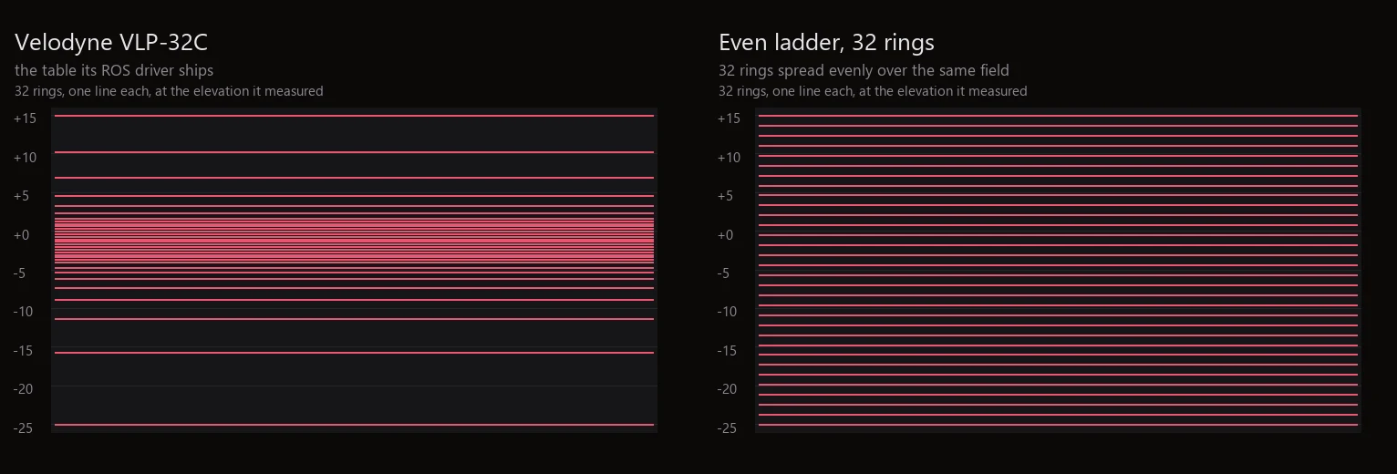
View the cloud from the side. Real heads show an uneven ladder with a dense band near the horizon. Evenly spaced rings mean the beam pattern is a guess.
A LiDAR scan is a set of rays fired in a known pattern, each returning the distance to the first thing it hits. A 3D scene knows every one of those distances exactly, which is why a synthetic cloud can carry a class on every single point, something no real scan has ever come with.
Every LiDAR head is a set of lasers at fixed vertical angles, spun about a vertical axis. Each laser fires many times per revolution, and each firing returns one point. Simulating that means choosing a direction for every firing and asking the scene what the ray hits, which a game engine is already built to answer quickly.
So the ray casting is the easy half. The half that decides whether the result resembles a real sensor is the pattern of directions, and that is where most synthetic clouds quietly stop being useful.
The obvious way to place thirty-two lasers across a forty-degree field is to space them evenly, a degree and a quarter apart. No manufacturer does this. Real heads crowd their beams near the horizon, where the road and the vehicles are, and leave wide gaps above and below.
The consequence is not cosmetic. A model trained on an evenly spread ladder learns a density profile that does not exist: it sees far more returns on the ground plane near the sensor and far fewer at the horizon than it will ever get in the field. The elevations are published in every sensor’s calibration file, so this is a gap that can simply be closed.
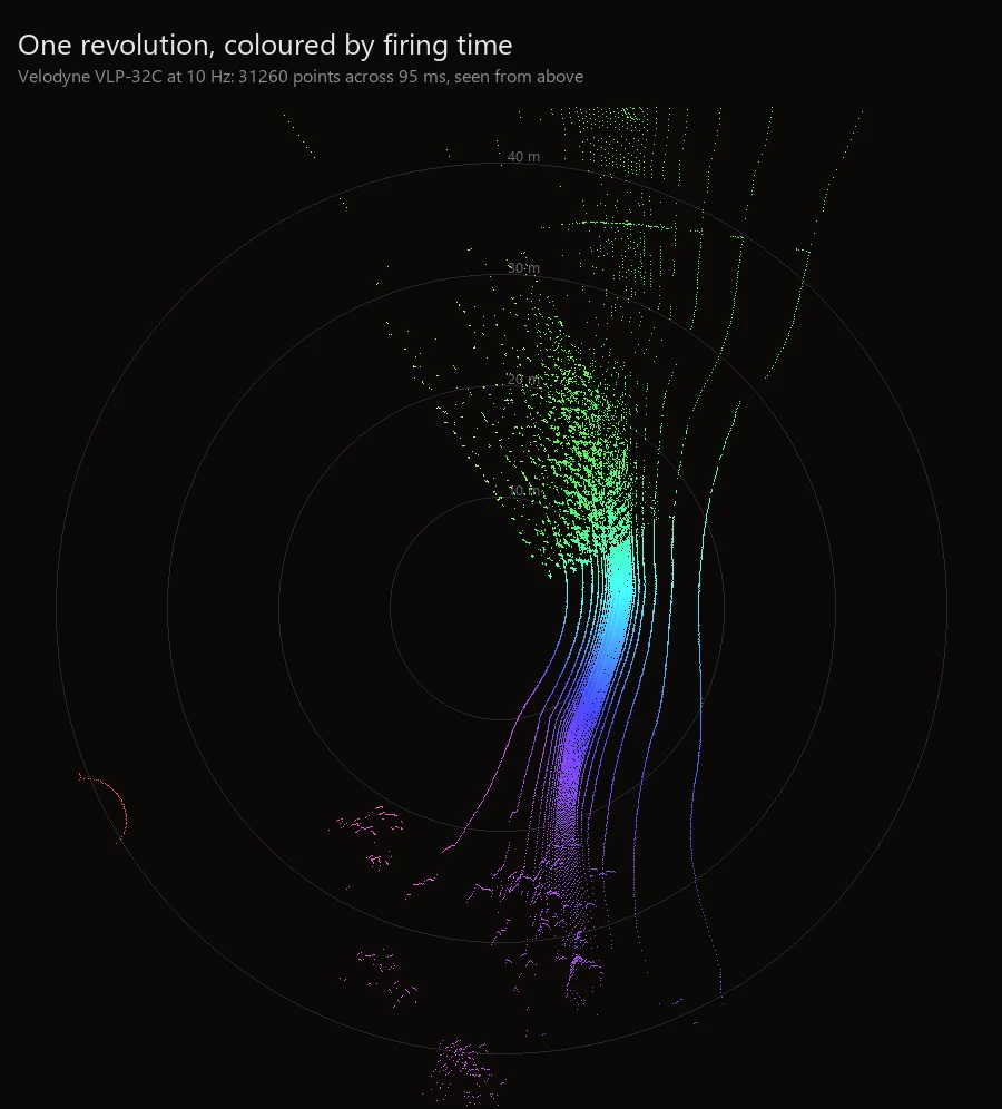
A head spinning at ten revolutions a second takes a tenth of a second to come round. A vehicle at fifty kilometres an hour travels most of a metre in that time. The points at the end of a revolution were therefore taken from a different place than the points at the start, and a cloud that ignores this is a cloud of a world that stood still.
Whether it matters depends entirely on what you are training. For a static scene survey, not at all. For anything mounted on something moving, it is the difference between a clean object and a smeared one, and a model trained without it will meet the smear for the first time in production.
Labelling a real point cloud means a human rotating a 3D view and drawing boxes around clusters of dots. It is slow, it is expensive, and at the edges of an object it is guesswork: which of these points belong to the pedestrian and which to the bollard behind them is a judgement call made in a viewport.
A synthetic scan has no edge case there. The ray hit a particular object; the engine knows which one; the class travels with the point. Every point is labelled, including the ones a human would never have bothered with, and the labelling costs nothing extra because it falls out of the same cast that produced the geometry.
Two formats cover most of what tooling expects. PLY is a plain point list with named properties, which is what viewers and Open3D want and what you should look at first. KITTI writes packed binary floats, four per point, and is what most published detection code loads without argument.
Whichever you choose, keep the per-point class as a separate array alongside rather than trying to smuggle it into the intensity channel. Intensity means something, and a pipeline that finds a class id in it will misbehave in a way that takes a day to find.
View the cloud from the side. Real heads show an uneven ladder with a dense band near the horizon. Evenly spaced rings mean the beam pattern is a guess.
A class with a handful of points across a whole capture will not train, and it is cheaper to find that in a histogram than after a run.
A scan taken from a different instant than the picture beside it describes a different world. The two should be written from the same moment, and a capture should say so rather than leave you to hope.
LiDAR is a modality of an ordinary capture rather than a separate tool, so it comes out of the same run as the frame, the depth and the labels, written from the same instant. Named sensor heads are scanned with the beam tables their calibration files describe rather than with an even ladder.
What it simulates and what it does not is set out in two tables on the LiDAR page, including the parts it does not model at all. Read that before deciding whether it fits your problem; it is more useful than another paragraph of claims here.